Cisco Packet Tracer: Star Topology
Cisco Packet Tracer: Star Topology - Notes and Summary
**Video Title:** Cisco Packet Tracer: Star Topology
**Channel:** Ramalingam Murugan
**Description:** Topologies: Star Topology
---
1. Summary
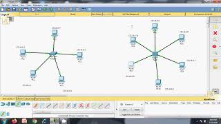
This video demonstrates the implementation and explanation of a star topology within Cisco Packet Tracer. It covers the fundamental concept of a star topology, its components (central device and end devices), how to set it up in Packet Tracer, and the basic configuration required for devices to communicate. The instructor emphasizes the ease of setup and troubleshooting associated with this topology.
---
2. Key Takeaways
* **Star Topology Definition:** A network topology where all end devices are connected to a central hub or switch.
* **Central Device:** A crucial element in a star topology, typically a switch or a hub.
* **End Devices:** Computers, laptops, printers, etc., that connect to the central device.
* **Packet Tracer Implementation:** The video provides a practical walkthrough of building a star topology in Cisco Packet Tracer.
* **Cabling:** Straight-through cables are used to connect end devices to the central switch.
* **Device Configuration:** Basic IP addressing is shown for end devices to enable communication.
* **Troubleshooting:** The star topology is noted for its ease of troubleshooting due to the central point of connection.
* **Scalability:** Adding or removing devices is straightforward.
---
3. Detailed Notes
**I. Introduction to Star Topology**
* Definition: A network setup where each node (end device) is connected to a central node (switch or hub).
* Analogy: Similar to the spokes of a wheel connecting to the hub.
**II. Components of a Star Topology**
* **Central Device:**
* Typically a **switch** (preferred for efficiency and intelligence) or a **hub** (older technology, broadcasts data to all ports).
* Acts as the central point for all network traffic.
* **End Devices:**
* Computers, laptops, servers, printers, etc.
* Each end device connects directly to the central device.
**III. Advantages of Star Topology**
* **Easy Installation & Cabling:** Straightforward to set up and manage.
* **Easy Troubleshooting:** If one cable or device fails, it typically only affects that specific node and the rest of the network remains functional. The central device makes it easy to isolate issues.
* **Scalability:** Easy to add new devices by connecting them to an available port on the central device.
* **Performance:** With a switch, each device has a dedicated connection, reducing collisions and improving performance compared to older bus topologies.
**IV. Disadvantages of Star Topology**
* **Central Point of Failure:** If the central device fails, the entire network goes down.
* **Cost:** Requires more cabling than some other topologies, and the cost of the central device can be a factor.
**V. Implementation in Cisco Packet Tracer**
* **Adding Devices:**
* Select the appropriate end devices (e.g., PCs, Laptops).
* Select a central device (e.g., a 2960 switch is commonly used).
* **Connecting Devices:**
* Use the **"Connections"** icon.
* Select the **"Copper Straight-Through"** cable.
* Click on the end device, choose a FastEthernet port.
* Click on the switch, choose an available FastEthernet port.
* Repeat for all end devices.
* Observe the link lights (green for active connection).
* **Basic Device Configuration (IP Addressing):**
* Click on each end device.
* Navigate to the **"Desktop"** tab.
* Go to **"IP Configuration"**.
* Manually assign an **IP Address** (e.g., 192.168.1.10 for the first PC, 192.168.1.11 for the second, etc.).
* Enter the corresponding **Subnet Mask** (e.g., 255.255.255.0).
* The default gateway is typically not configured for simple end-to-end PC-to-PC communication within the same subnet unless routing is involved, but for a basic setup, it can be left blank or set to the switch's management IP if applicable (though not explicitly shown for device-to-device communication in this video context).
* **Verification of Connectivity:**
* Use the **"Ping"** command from the Command Prompt on one end device to another.
* Example: `ping 192.168.1.11` (from PC1 to PC2).
* Successful pings (reply from target) confirm that the devices are communicating.
* Unsuccessful pings (request timed out) indicate a configuration or connectivity issue.
**VI. Troubleshooting Scenarios (Conceptual)**
* **No link light:** Check the cable connection at both ends and ensure the correct cable type (straight-through) is used.
* **Link lights on, but no ping:** Verify IP addresses and subnet masks are correctly configured and within the same network segment. Check for typos.
* **Specific device failure:** If one PC cannot communicate, check its configuration. If the central switch fails, the entire network is down.
---
Related Summaries
![[캡컷PC]0015-복합클립만들기분리된영상 하나로 만들기](https://img.youtube.com/vi/qtUfil0xjCs/mqdefault.jpg)

Why this video matters
This video provides valuable insights into the topic. Our AI summary attempts to capture the core message, but for the full nuance and context, we highly recommend watching the original video from the creator.
Disclaimer: This content is an AI-generated summary of a public YouTube video. The views and opinions expressed in the original video belong to the content creator. YouTube Note is not affiliated with the video creator or YouTube.